Intro
The Pierre Auger Observatory in Malargüe, Argentina is the world's largest and most sensitive detector of Ultra-High Energy Cosmic Rays. Auger is specifically designed to measure detailed properties of a statistically large sample of the highest energy cosmic rays, and thereby provide a major push toward resolving the puzzle of their origins. The Auger Observatory measures air shower events to reconstruct the energy, arrival direction and some information on the atomic composition for each primary cosmic ray detected. By carefully analyzing the distributions of such reconstructed properties, we can constrain and perhaps ultimately identify these astrophysical sources.
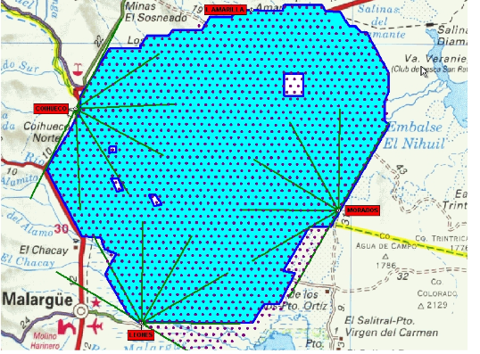 Deployment of the baseline Auger Observatory in Argentina has been essentially complete since early 2008. Here we show a map of the positions of surface detector array and the fluorescence detector system during most of 2011. Blue dots show the approximately 1,650 Surface Detectors (SD) stations. The green lines show the viewing directions for all four Fluorescence Detector (FD) buildings. Overall, the array covers an area of more than 3,000 square kilometers. At present, all subsystems on the array are working well. The collaboration has effectively constructed the array in Argentina very nearly on budget and on time. Operations costs for the array continue to match expected levels.
Wireless Telecommunications
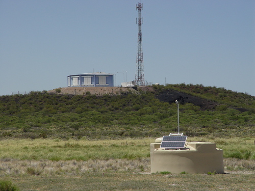
Since 2007, our PI has served on the Auger Technical Board as the Task Leader for wireless telecommunications (Comms), dealing with the extensive wireless LAN network connecting all detectors to the central campus. Our PI has direct and ongoing responsibility for the operation and performance of the surface detector station wireless radio transmitters, along with four communications towers, and the asso- ciated microwave backbone data transfer system. Our PI also works with Observatory staff to maintain and troubleshoot all related wireless communication issues on site, including voice Comms (walkie-talkie), point-to-point 2.4 GHz data relays, and site WiFi. During 2010, a comprehensive Operational Readiness Review (ORR) was successfully concluded by the Pierre Auger Project Management to confirm that the Comms system is working properly and is well-supported for years of future operation in Auger.
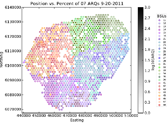 Additionally, the HEA group at CWRU directly supports the Auger Comms subtask as the lead team for Comms system Performance Monitoring. Our group has primary responsibility for monitoring and archiving all Comms performance diagnostics. Comms Monitoring is a critical and time-consuming task that involves the daily efforts of nearly everyone in the HEA group, including undergraduate students. We have developed a comprehensive set of bench-marks and graphical diagnostics tools to help us identify and correct a wide range of potential Comms instrument problems that could have a negative impact on Auger science data. For example, the color coding on this array map indicates the rate of data errors as a function of station location. Using this map, it is easy to identify and troubleshoot a intermittent problem with one of the tower base-station units located in the northern part of the array. The near-real-time performance monitoring of the Comms system that has been carried out at CWRU is now being integrated into the main Auger Observatory Monitoring system at the Malargüe site.
Surface Detector Instrumentation
Case Western has a history of supporting instrumentation programs for the Surface Detector Electronics (SDE) sub-task on Auger. More than 1,700 GPS receiver units that have been used for deployment in the Auger SD stations have been tested and calibrated by the HEA group at CWRU. Our group also completed thermal stress testing on several tank components including Auger Tank Power Control Boards (TPCBs). Details have been described in past reports to the NSF. The HEA group continues to support detector instrumentation by diagnosing and repairing broken electronics components, particularly GPS receivers and TPCBs.
Portable Dual-Channel Time Tagging
 In addition to the development and testing of instrumental subsystems deployed at surface detectors, the HEA group has also been very active in the development of unique test equipment for important in-the-field calibrations. For example, the Case Western HEA group designed and fabricated two portable GPS time- tagging systems that can be used to measure absolute timing of arbitrary asynchronous TTL input pulses on each of two channels to an accuracy of better than 20 nanoseconds (GPS time). The HEA group has used these portable time tagging systems together with a portable PMT system to measure and synchronize the arrival times of laser light flashes at both SD and FD systems. This provides for a direct measurement and localization of the SD-FD timing offset which is a critical parameter for Auger hybrid reconstruction. By measuring this offset with precision, we effectively calibrate out what would otherwise be a major systematic uncertainty in our hybrid event reconstruction analysis.
Advanced Time Tagging
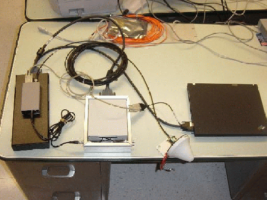
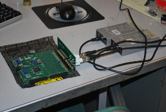 The GPS receivers originally deployed to the Auger South array (Motorola Oncore UT+) are now obsolete and a more accurate system is required for the future which is based on a more recent and more precise GPS receiver, the I-Lotus M12M. Anticipating the need to test and calibrate new GPS receivers, we have initiated development of a new test bench to match the required timing accuracy of the newer receivers. We have designed and fabricated a prototype test system based on the Xilinx XC2XL PLD logic board that can operated with a counter frequency as high as 150 to 200 MHz. The photo here shows the prepared circuit board along with a custom-designed daughter-board socket for the new, faster oscillators. Within the past two years, CWRU has successfully implemented this design so that we now have a working test stand which is already being used to verify the performance of new GPS receivers to a precision of better than 4 nanoseconds.